สินค้าทั้งหมด


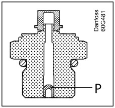
The integrated pulse snubber protects the sensor from cavitation, liquid hammer, and pressure peaks that may occur in fluid systems when flow velocity changes rapidly—for example, during fast valve closure or when pumps start and stop.
These phenomena can occur on both the inlet and outlet sides of a system, even in low operating-pressure applications. Fluid viscosity has only a minor influence on response time; even at viscosities up to 100 cSt, the response time remains below 4 ms.
Figure 1: Integrated pulse snubber (Pulse-snubber)
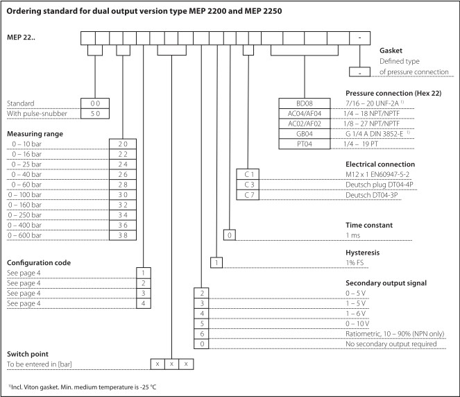
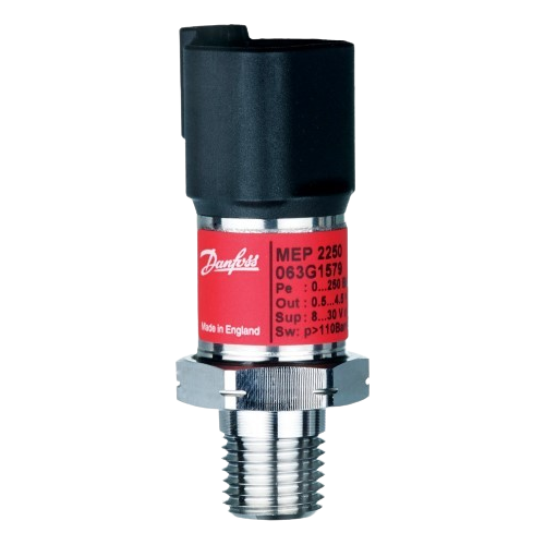
| Type | MEP 2200 and MEP 2250 |
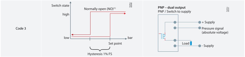
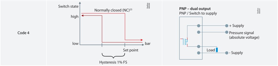
| Dual output (Switch and Analogue – output) | |
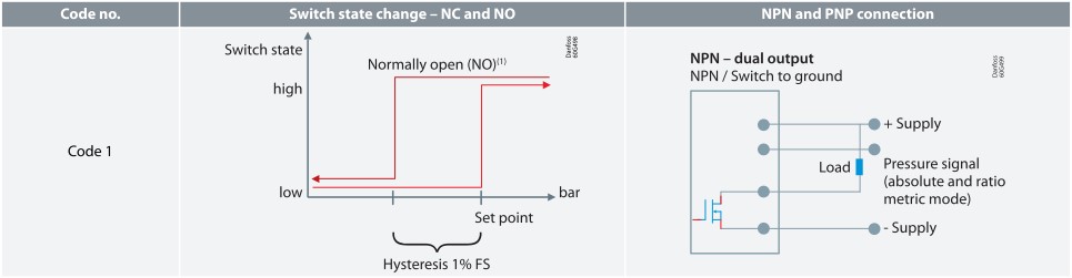
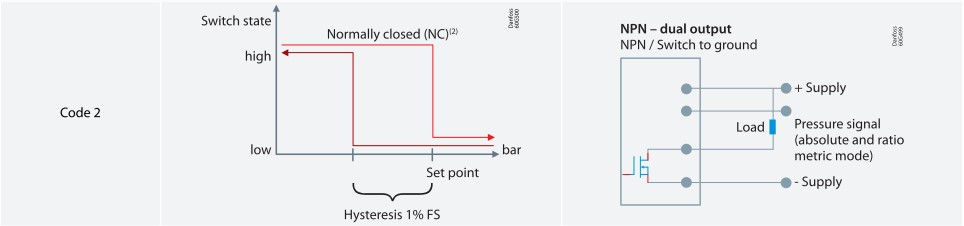
| Switch Hysteresis | ~ 1% FS(1) |
| Switch Time delay | 1 ms |
| Accuracy (incl. non-linearity, hysteresis and repeatability) |
2% FS |
| Thermal accuracy | < ± 0.15% FS / 10K |
(1)For detailed information please contact Danfoss.
| Features | Values | |||||||||||||
| Nominal pressure[bar] | 10 | 16 | 25 | 40 | 60 | 100 | 160 | 250 | 400 | 500 | 600 | 1000(2) | 1600(2) | 2200(2) |
| Overload pressure | 30 | 48 | 80 | 80 | 140 | 200 | 320 | 500 | 800 | 1400 | 1400 | 2000 | 2500 | 3000 |
| Burst pressure | 400 | 640 | 800 | 800 | 1400 | 2000 | 1600 | 2500 | 4000 | >4000 | >4000 | >4000 | >4000 | >4000 |
(2)Only available wih M12 × 11.5 P high pressure port, type FC06. Please contact Danfoss.
| Features | Values | ||||||||||
| Nominal pressure [bar] | 10 | 16 | 25 | 40 | 60 | 100 | 160 | 250 | 400 | 500 | 600 |
| Overload pressure | 30 | 48 | 120 | 120 | 210 | 300 | 480 | 750 | 1200 | 2100 | 2100 |
| Burst pressure | 400 | 640 | 800 | 800 | 1400 | 2000 | 1600 | 2500 | 4000 | >4000 | >4000 |
| Type | MEP 2200 and MEP 2250 |
| Dual output (Switch and Analogue – output) | |
| Max. load(3) | 500 mA |
| Electrical connector types | See Electrical connections |
| Max. inrush load | 1.6 A |
| Supply voltage | 8 – 32 V |
| Over/reverse voltage | ± 36 V |
(3)For inductive load limits, please contact Danfoss.
| Nom. output signal (Short-circuit protected) | NPN and PNP | NPN | |
| 0 – 5, 1 – 5, 1 – 6 V | 0 – 10 V | 10 – 90% ratiometric | |
| Supply voltage [UB], polarity protected | 8 – 32 V | 12 – 32 V | – |
| Supply – current consumption | 4.5 mA | 4.5 mA | 4.5 mA |
| Output inpedance | ≤ 90 Ω | ≤ 90 Ω | ≤ 90 Ω |
| Load [RL] (connected to 0 V) | RL ≥ 10 kΩ | RL ≥ 10 kΩ | RL ≥ 5 kΩ |
| Load [RL] (connected to + V) | Not possible | Not possible | RL ≥ 5 kΩ |
| Features | Values | |
| Media temperature range | – 40 – 125 °C | |
| Ambient temperature range | – 40 – 125 °C | |
| Compensated temperature range | – 40 – 125 °C | |
| Transport temperature range | -55 – 150 °C | |
| EMC – Emission | EN 61326-2-3: 2013 | |
| EMC Directive | 2014/30/EU | |
| EMC – Immunity RF field | 100 V/m, 26 Mhz – 1 GHz | EN 61326-2-3 Cable < 30 m |
| 3 V/m, 1.4 GHz – 2.7 GHz | ||
| Electrical performance comply with | ISO 7637 pulse 1 – 4 V (MEP 26XX) | |
| ISO 7637-2 / ISO 16750 (MEP 22XX) (pulse 5b <45 V) | ||
| Vibration stability | 20 g, 10 – 2000 Hz, sinus | EN 60068-2-6 |
| Shock resistance | 100 g | EN 60068-2-27 |
| Materials | |
| Wetted parts | 17 – 4 PH |
| Enclosure | AISI 304 or plastic |
| Pressure connection | 17 – 4 PH |
| Electrical connection | See Electrical connections |


HEX is 22 mm across flats.